Posted on Leave a comment

Multiple MCP23017 Expanders With Interrupts Not Playing Nice

was manually polling my 3 MCP23017 expanders I need for all the buttons for my synth just to get the ball rolling. The serial monitor tells me it was taking almost 5ms….which is similar to the amount of time it’ll take for the dinosaurs to come back. (It’s a billion years in microcontroller land.) I thought making the jump to interrupts wouldn’t be that big of a deal. It was an absolute nightmare. I found a site that really got me going https://www.best-microcontroller-projects.com/mcp23017.html#L2415 , but they pulled a few tricks to account for some goofiness in the I2C’s interrupts. Within their tricks was a 1ms debounce delay. I’ve done my share of debouncing and I immediately did the ol’ nose scrunch to that one. A 1ms debounce is totally non-functional.

My problem was that after an interrupt was triggered on the MCP23017 (causing the 5V to drop to 0V), it was staying at 0V and not being reset. Using the Adafruit library, the method to do that was to simply read the getLastInterruptPinValue(); The problem was I was already doing this and the pin was not resetting back to 5V.

The solution came in realizing that the interrupts in the MCP23017 were continually being triggered by switch bounce. Nick Gammon, the king of everything, has an outstanding tutorial that illustrates this.  He uses no oddball ISR stuff…..just meat n’ taters interrupts. However, he uses a 500ms debounce. That’s a hair extreme, but it sure beats 1ms. I was lucky in that I could wait to call the getLastInterruptPinValue() until I was done doing my work. In fact, I had no need for the value.  All mine are zero.   I was using that function call as an ISR reset. So, I could call getLastInterruptPin(), do my work, put a delay(150) just before the clearing function and everyone is happy.

Even better, I’m using the switches connected to my 3 MCP23017s to update a 16×2 LCD (among other things). I can update the LCD instantaneously. I don’t have to wait at all. In this way, the end-user will never feel my LCD being slow or clunky even though I have delays built-in.  If I wanted to get really cute (and I may) and use an asynchronous delay like the infamous Arduino Blink Without Delay example. Actually, I’ll probably have to do that.

Anyway, here’s the code. I hope it helps.


#include "Arduino.h"


#include 
#include 


#define BUTTON1_INT_PIN PB8
#define BUTTON2_INT_PIN PB9
#define BUTTON3_INT_PIN PA15
#define MCP_INT_MIRROR true // Mirror inta to intb.
#define MCP_INT_ODR false   // Open drain.


/********** NOTES ********************/
Adafruit_MCP23017 button1; // Create an object for the first button board.
Adafruit_MCP23017 button2; // Create an object for the second button board.
Adafruit_MCP23017 button3; // Create an object for the third button board.

volatile byte button1Apushed, button1A_ID_value, button2Apushed, button2A_ID_value, button3Apushed, button3A_ID_value;
volatile byte button1A_ID = 16; // reset to be out of the range of the 0-15 MCP23017 buttons.
volatile byte button2A_ID = 16; // reset to be out of the range of the 0-15 MCP23017 buttons.
volatile byte button3A_ID = 16; // reset to be out of the range of the 0-15 MCP23017 buttons.

// ------------- FUNCTIONS ---------------------------

void button1A_ISR()
{
  button1Apushed = 1;
}

void button2A_ISR()
{
  button2Apushed = 1;
}

void button3A_ISR()
{
  button3Apushed = 1;
}


void setup()
{
  //---------------- BUTTON EXPANDER SETUP ------------------------
  // The address is specified using the A0, A1, and A2 pins
  button1.begin(0b000); // use default address 0, otherwise, the address needs to be defined
  button2.begin(0b001); // make sure to give A0 5V.
  button3.begin(0b010); // Set this up.

  pinMode(BUTTON1_INT_PIN, INPUT); // button1 interrupt pin on ucontroller
  pinMode(BUTTON2_INT_PIN, INPUT); // button1 interrupt pin on ucontroller
  pinMode(BUTTON3_INT_PIN, INPUT); // button1 interrupt pin on ucontroller

  for (int i = 0; i < 16; i++)
  {
    button1.pinMode(i, INPUT); // MCP23017 #1 pins are set for inputs
    button1.pullUp(i, HIGH);   // turn on a 100K pullup internally
    button2.pinMode(i, INPUT); // MCP23017 #2 pins are set for inputs
    button2.pullUp(i, HIGH);   // turn on a 100K pullup internally
    button3.pinMode(i, INPUT); // MCP23017 #2 pins are set for inputs
    button3.pullUp(i, HIGH);   // turn on a 100K pullup internally
  }
  
  button1.setupInterrupts(MCP_INT_MIRROR, MCP_INT_ODR, LOW); // The mcp output interrupt pin.
  button2.setupInterrupts(MCP_INT_MIRROR, MCP_INT_ODR, LOW); // The mcp output interrupt pin.
  button3.setupInterrupts(MCP_INT_MIRROR, MCP_INT_ODR, LOW); // The mcp output interrupt pin.

  // Setup INTs on the MCP23017 button1 for all 16 buttons
  for (int i = 0; i < 16; i++)
  {
    button1.setupInterruptPin(i, FALLING);
    button2.setupInterruptPin(i, FALLING);
    button3.setupInterruptPin(i, FALLING);
  }

  button1.readGPIOAB();
  button2.readGPIOAB();
  button3.readGPIOAB();
  
  attachInterrupt(digitalPinToInterrupt(BUTTON1_INT_PIN), button1A_ISR, FALLING);
  attachInterrupt(digitalPinToInterrupt(BUTTON2_INT_PIN), button2A_ISR, FALLING);
  attachInterrupt(digitalPinToInterrupt(BUTTON3_INT_PIN), button3A_ISR, FALLING);


} // end of setup

void loop()
{

  if (button1Apushed)  // Buttons 0-15 on MCP23017 #1 
  {
    button1A_ID = button1.getLastInterruptPin();
	
	// update LDC here

    button1A_ID = 16;                                                                   // reset to a value that is outside the 0-15 button range of the MCP23017
    button1Apushed = 0;                                                                 // reset the pushed status
    delay(150);                                                                         // strong debounce
    button1A_ID_value = button1.getLastInterruptPinValue();                             // This one resets the interrupt state as it reads from reg INTCAPA(B).
    attachInterrupt(digitalPinToInterrupt(BUTTON1_INT_PIN), button1A_ISR, FALLING);
  }

  if (button2Apushed) // Buttons 16-31 on MCP23017 #2
  {
    button2A_ID = button2.getLastInterruptPin() + 16;


	// update LDC here
	
    button2A_ID = 16;                                                                   // reset to a value that is outside the 0-15 button range of the MCP23017
    button2Apushed = 0;                                                                 // reset the pushed status
    delay(150);                                                                         // strong debounce
    button2A_ID_value = button2.getLastInterruptPinValue();                             // This one resets the interrupt state as it reads from reg INTCAPA(B).
    attachInterrupt(digitalPinToInterrupt(BUTTON2_INT_PIN), button2A_ISR, FALLING);
  }
  if (button3Apushed) //Buttons 32-47 on MCP23017 #3
  {
    button3A_ID = button3.getLastInterruptPin() + 32;
	
	// update LDC here

    button3A_ID = 16;                                                                   // reset to a value that is outside the 0-15 button range of the MCP23017
    button3Apushed = 0;                                                                 // reset the pushed status
    delay(150);                                                                         // strong debounce
    button3A_ID_value = button3.getLastInterruptPinValue();                             // This one resets the interrupt state as it reads from reg INTCAPA(B).
    attachInterrupt(digitalPinToInterrupt(BUTTON3_INT_PIN), button3A_ISR, FALLING);
  }
}
Posted on Leave a comment

Why Are All These Resistors Thru-Hole? Isn’t SMD Cooler?

SMD is cooler….when a machine does all the work. At the prototyping phase (and assuming you don’t have all the fancier tools specific to the tiny world of SMD), SMD parts take longer to solder, often require a heat gun to remove, and offer no convenient place to hook your oscilloscope probe to. Bodge wires with any hint of durability are much more difficult and time-consuming in SMD land. In short, compared to thru-hole resistors, SMD resistors are a total pain if a person is engaged in an epic battle. If your battle isn’t all that epic, it won’t matter, but who the hell meddles with non-epic battles?

I learned this the hard way in my senior Capstone project back in engineering school. I had a 100mm x 100mm PCB board with a gigazillion components on it. We used a simple voltage divider before an op-amp to scale our voltage for reading with an ADC. All I had to do was swap out 2 resistors to accommodate us moving up to a much larger voltage. This is something that would have taken me 1-2 minutes if I had all the right tools and 2-3 minutes almost the right tools with thru-hole. My school wasn’t equipped for SMD parts. I had to bring in my heat gun from home. Because the board layout was so tight, even with plenty of Kapton tape to protect the good components, I ended up blowing off 4 or 5 extra components off the board. (I was in a rush. That didn’t help.) Of course, these were specific SMD components and I was crawling around the floor looking for them. In the end, the whole mess could have been avoided if I had just used thru-hole resistors.

Obviously, most of the best chips these days are SMD and many of them offer no DIP-style thru-hole option. In those cases, I’ll gladly use the SMD chip and then break it out with 2.54mm header pins and such to allow for maximum protectivity in battle.

Posted on Leave a comment

Serial USARTs On STM32 Blue Pill With Arduino Code in PlatformIO

Here’s the “Hello World” edition of getting access to USART2 and USART3 on an STM32 Blue Pill in PlatformIO using the Arduino framework.


/* lib_deps = NONE
  # Using a library name

-------- Platform.ini Settings----------
[env:bluepill_f103c8]
platform = ststm32
board = bluepill_f103c8
#board = bluepill_f103c8
framework = arduino
upload_protocol = stlink
lib_compat_mode = soft

*/

#include "Arduino.h"
HardwareSerial Serial2(USART2);   // PA3  (RX)  PA2  (TX)
HardwareSerial Serial3(USART3); // PB11 (RX)  PB10   (TX)

void setup() {
Serial.begin(19200);   // PA10  (RX) PA9 (TX) 
Serial2.begin(19200);  // PA3  (RX)  PA2  (TX)
Serial3.begin(19200);  // PB11 (RX)  PB10   (TX)

Serial.println("Serial: 1");
Serial2.println("Serial2: 2");
Serial3.println("Serial3: 3");
}

void loop() {
Serial.println("Serial: 1");
Serial2.println("Serial2: 2");
Serial3.println("Serial3: 3");
delay(1000);
}
Posted on Leave a comment

STM32 Blue Pill ADC Values Too Low in PlatformIO


I kept getting values that were way too low when feeding an ADC on the STM32 Blue Pill 3.3V. I should have been getting values that were around 4000 and instead I was closer to 800.

Solution
1) The default ADC in the Arduino library is set to 10-bit resolution. This is what you normally get with analogRead(). To change it, put this in your setup(). Read more about it here: https://www.arduino.cc/reference/en/language/functions/zero-due-mkr-family/analogreadresolution/

analogReadResolution(12);

Notes
— This would have been a much easier problem to solve if i had been getting values of around 1000. It turns out that my ADC pin wasn’t getting exactly 3.3V. There was a voltage drop in my system – I’ve got a huge mess currently hooked to the Blue Pill – that knocked it down to around 3V. Normally, calculating bit resolution in decimal is 2^x – 1. So 2^10 – 1 = 1023.

— PlatformIO had nothing to do with the error. I’m new to PlatformIO and never know if my issues are due to the STM32’s specific needs, the Arduino library, or some kind of PlatformIO specific issue. It seems that as long as the hardware is setup correctly and
#include <Arduino.h>
is at the top of the program/sketch/whatever, PlatformIO has no ill effects. The problems I have had aren’t the fault of PlatformIO but from adapting libraries intended for AVR to STM32F1.


Posted on Leave a comment

Genuine STM32 Blue Pill vs CS32F103C8T6 Clone

I’m troubleshooting a synth design and looking at the data on the SPI bus.  I have 10 STM32 clones (CS32F103C8T6) of the STM32F103C8T6 around and decided to try them out since they have the correct USB resistor.

I was getting the following error in PlatformIO.

Warn : UNEXPECTED idcode: 0x2ba01477

To get the clone to work, I had to change stm32f1x.cfg which I found in C:\Users\YOUR_WINDOWS_USER\.platformio\packages\tool-openocd\scripts\target\

I changed set _CPUTAPID 0x1ba01477 to set _CPUTAPID 0x2ba01477.  If I need to go back to the real Blue Pill, I’ll have to change this back again.

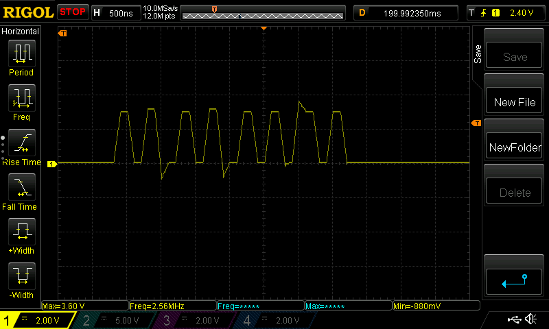
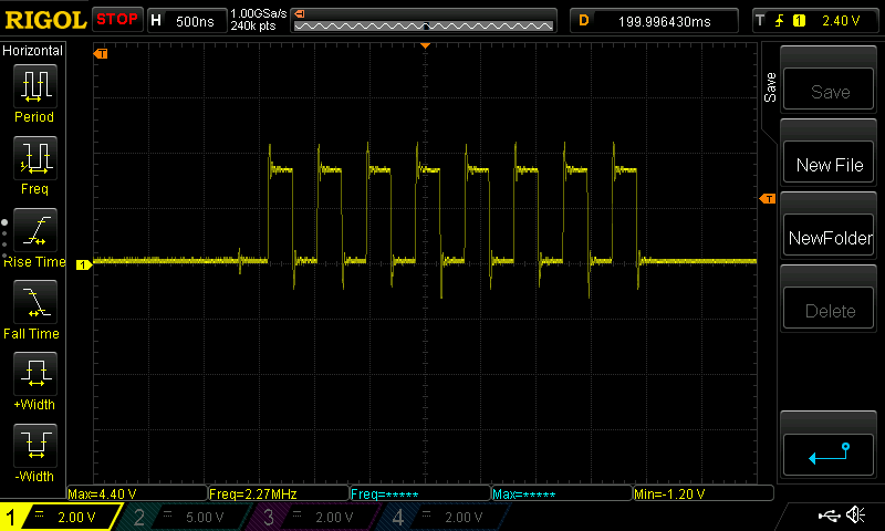
I started with the clone and then switched to the real one.  The scope shows some interesting results.  This is data from the SPI bus.  The circuit is 100% identical in both cases.

CS32F103C8T6 Clone SPI Data

Genuine STM32F103C8T6 SPI Data

I’m not sure if the clone just can’t handle the speed or if there’s some kind capacitance slowing it down.  Regardless, the SPI output of the clone is so bad that I’ll have to check the timing diagrams for my SPI-receiving chip.  I don’t have this problem with the genuine STM32.

If anyone knows a solution to get the clone to behave, please tell me.  Otherwise, I’ll have to view these Chinese clones as WAY too expensive once time is factored in.