Posted on Leave a comment

STM32 Blue Pill ADC Values Too Low in PlatformIO


I kept getting values that were way too low when feeding an ADC on the STM32 Blue Pill 3.3V. I should have been getting values that were around 4000 and instead I was closer to 800.

Solution
1) The default ADC in the Arduino library is set to 10-bit resolution. This is what you normally get with analogRead(). To change it, put this in your setup(). Read more about it here: https://www.arduino.cc/reference/en/language/functions/zero-due-mkr-family/analogreadresolution/

analogReadResolution(12);

Notes
— This would have been a much easier problem to solve if i had been getting values of around 1000. It turns out that my ADC pin wasn’t getting exactly 3.3V. There was a voltage drop in my system – I’ve got a huge mess currently hooked to the Blue Pill – that knocked it down to around 3V. Normally, calculating bit resolution in decimal is 2^x – 1. So 2^10 – 1 = 1023.

— PlatformIO had nothing to do with the error. I’m new to PlatformIO and never know if my issues are due to the STM32’s specific needs, the Arduino library, or some kind of PlatformIO specific issue. It seems that as long as the hardware is setup correctly and
#include <Arduino.h>
is at the top of the program/sketch/whatever, PlatformIO has no ill effects. The problems I have had aren’t the fault of PlatformIO but from adapting libraries intended for AVR to STM32F1.


Posted on Leave a comment

Genuine STM32 Blue Pill vs CS32F103C8T6 Clone

I’m troubleshooting a synth design and looking at the data on the SPI bus.  I have 10 STM32 clones (CS32F103C8T6) of the STM32F103C8T6 around and decided to try them out since they have the correct USB resistor.

I was getting the following error in PlatformIO.

Warn : UNEXPECTED idcode: 0x2ba01477

To get the clone to work, I had to change stm32f1x.cfg which I found in C:\Users\YOUR_WINDOWS_USER\.platformio\packages\tool-openocd\scripts\target\

I changed set _CPUTAPID 0x1ba01477 to set _CPUTAPID 0x2ba01477.  If I need to go back to the real Blue Pill, I’ll have to change this back again.

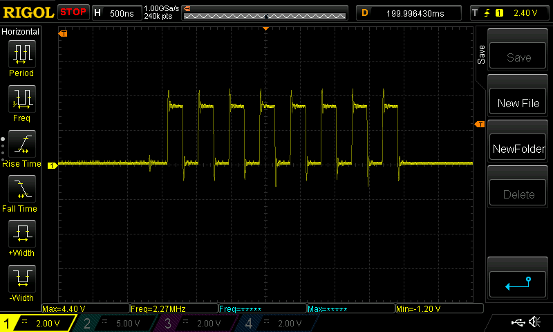
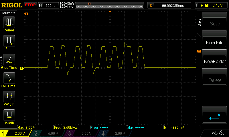
I started with the clone and then switched to the real one.  The scope shows some interesting results.  This is data from the SPI bus.  The circuit is 100% identical in both cases.

CS32F103C8T6 Clone SPI Data

Genuine STM32F103C8T6 SPI Data

I’m not sure if the clone just can’t handle the speed or if there’s some kind capacitance slowing it down.  Regardless, the SPI output of the clone is so bad that I’ll have to check the timing diagrams for my SPI-receiving chip.  I don’t have this problem with the genuine STM32.

If anyone knows a solution to get the clone to behave, please tell me.  Otherwise, I’ll have to view these Chinese clones as WAY too expensive once time is factored in.

Posted on Leave a comment

Add 32 Buttons With Just 2 Pins With MCP23017 Expander

I need about 40 buttons for my synth project.  I’m trying to run the entire synth with a single STM32 Blue Pill.  I’ve already shown how I can run 256 LEDs with 3 pins LINK IT HERE.  Since the MCP23017 is I2C, I could possibly run 128 buttons on 2 pins.  For now, I’m just running two of my Tactile Switch Female Dog boards (each with 16 buttons and a MCP23017 chip).

Stuff I Didn’t Know Yesterday About The MCP23017 Expander

  • I needed to power cycle this chip quite a bit when it didn’t act as expected.  If you start to lose your mind, go ahead and lose it.  Then kill the power for a second.
  • When using the internal pullups, we are in active low land.  Pushing the button gives a zero.  That’s normal.  I got confused when using the onboard STM32 Blue Pill LED as the stupid thing is also active low.  Apparently, I can handle only one active low thing per week.

I debated whether I wanted to use a library or just bang it out with Wire commands.  It’s really all the same, but I guess the library saves 2 seconds of work (at what cost?).  I opted for the Adafruit MCP23017 library, but I’m keeping a link close by for the tutorial using Wire so I don’t have to think or open a datasheet today.

Code For A Single MCP23017 Expander

#include <Arduino.h>
#include <Wire.h>
#include <Adafruit_MCP23017.h>
 
#define ONBOARD_LED PC13
 
// Connect pin #12 of the expander to PB6  I2C clock
// Connect pin #13 of the expander to PB7  I2C data
 
Adafruit_MCP23017 mcp;
 
void setup()
{
    // The address is specified using the A0, A1, and A2 pins
    mcp.begin(); // use default address 0, otherwise, the address needs to be defined
 
    for (int i = 0; i < 16; i++)
    {
        mcp.pinMode(i, INPUT); // MCP23017 pins are set for inputs
        mcp.pullUp(i, HIGH);   // turn on a 100K pullup internally
        delay(10);
    }
    pinMode(ONBOARD_LED, OUTPUT); // use the c13 LED as debugging
 
    // Sanity check to confirm functionality with onboard LED
    for (int i = 0; i < 8; i++)
    {
        digitalWrite(ONBOARD_LED, HIGH);
        delay(100);
        digitalWrite(ONBOARD_LED, LOW);
        delay(100);
    }
}
 
void loop()
{
 
    // Check for a button press of any button.  A LOW indicates a button press
    if (mcp.digitalRead(0) == 0 ||
        mcp.digitalRead(1) == 0 ||
        mcp.digitalRead(2) == 0 ||
        mcp.digitalRead(3) == 0 ||
        mcp.digitalRead(4) == 0 ||
        mcp.digitalRead(5) == 0 ||
        mcp.digitalRead(6) == 0 ||
        mcp.digitalRead(7) == 0 ||
        mcp.digitalRead(8) == 0 ||
        mcp.digitalRead(9) == 0 ||
        mcp.digitalRead(10) == 0 ||
        mcp.digitalRead(11) == 0 ||
        mcp.digitalRead(12) == 0 ||
        mcp.digitalRead(13) == 0 ||
        mcp.digitalRead(14) == 0 ||
        mcp.digitalRead(15) == 0)
    {
        digitalWrite(ONBOARD_LED, LOW); // Turn on the dumb, active low PC13 onboard LED
        delay(1000);                    // Keep the LED on a second.
    }
    else
    {
        digitalWrite(ONBOARD_LED, HIGH); // Turn off the dumb, active low PC13 onboard LED
    }
}

Code For 2 Simultaneous MCP23017 Expanders (32 Buttons)

#include <Arduino.h>
#include <Wire.h>
#include <Adafruit_MCP23017.h> 

#define ONBOARD_LED PC13

/********** HARDWARE *****************/
// Connect pin #12 of the expander to PB6  I2C clock
// Connect pin #13 of the expander to PB7  I2C data
// Remember that I2C requires pullups on clock and data pins.
// I used 2.2k resistors because I mindlessly read it on the internet
// From a guy who typed wth confidence

/********** NOTES ********************/
// If the board acts stupid and you don't want to blame yourself,
// power cycle your microcontroller and the MCP23017

Adafruit_MCP23017 mcp1; // Create an object for the first board.
Adafruit_MCP23017 mcp2; // Create an object for the second board.

void setup()
{
    // The address is specified using the A0, A1, and A2 pins
    mcp1.begin();    // use default address 0, otherwise, the address needs to be defined
    mcp2.begin(001); // make sure to give A0 5V.

    for (int i = 0; i < 16; i++)
    {
        mcp1.pinMode(i, INPUT); // MCP23017 #1 pins are set for inputs
        mcp1.pullUp(i, HIGH);   // turn on a 100K pullup internally
        mcp2.pinMode(i, INPUT); // MCP23017 #2 pins are set for inputs
        mcp2.pullUp(i, HIGH);   // turn on a 100K pullup internally
    }
    pinMode(ONBOARD_LED, OUTPUT); // use the c13 LED as debugging

    // Sanity check to confirm functionality with onboard LED
    for (int i = 0; i < 8; i++)
    {
        digitalWrite(ONBOARD_LED, HIGH);
        delay(75);
        digitalWrite(ONBOARD_LED, LOW);
        delay(75);
    }
}

void loop()
{

    // Check for a button press of any button.  A LOW indicates a button press
    // There is surely a smarter way to do this, but that never stopped me.
    if (mcp1.digitalRead(0) == 0 ||
        mcp1.digitalRead(1) == 0 ||
        mcp1.digitalRead(2) == 0 ||
        mcp1.digitalRead(3) == 0 ||
        mcp1.digitalRead(4) == 0 ||
        mcp1.digitalRead(5) == 0 ||
        mcp1.digitalRead(6) == 0 ||
        mcp1.digitalRead(7) == 0 ||
        mcp1.digitalRead(8) == 0 ||
        mcp1.digitalRead(9) == 0 ||
        mcp1.digitalRead(10) == 0 ||
        mcp1.digitalRead(11) == 0 ||
        mcp1.digitalRead(12) == 0 ||
        mcp1.digitalRead(13) == 0 ||
        mcp1.digitalRead(14) == 0 ||
        mcp1.digitalRead(15) == 0 ||
        mcp2.digitalRead(0) == 0 ||
        mcp2.digitalRead(1) == 0 ||
        mcp2.digitalRead(2) == 0 ||
        mcp2.digitalRead(3) == 0 ||
        mcp2.digitalRead(4) == 0 ||
        mcp2.digitalRead(5) == 0 ||
        mcp2.digitalRead(6) == 0 ||
        mcp2.digitalRead(7) == 0 ||
        mcp2.digitalRead(8) == 0 ||
        mcp2.digitalRead(9) == 0 ||
        mcp2.digitalRead(10) == 0 ||
        mcp2.digitalRead(11) == 0 ||
        mcp2.digitalRead(12) == 0 ||
        mcp2.digitalRead(13) == 0 ||
        mcp2.digitalRead(14) == 0 ||
        mcp2.digitalRead(15) == 0

    )
    {
        digitalWrite(ONBOARD_LED, LOW); // Turn on the dumb, active low PC13 onboard LED
        delay(1000);                    // Keep the LED on a second.
    }
    else
    {
        digitalWrite(ONBOARD_LED, HIGH); // Turn off the dumb, active low PC13 onboard LED
    }
}
Posted on Leave a comment

140 Resistor Labels for 3D Printed Organizer

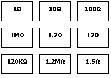
I created paper labels for the E24 Series Resistor Storage Solution on Thingiverse. I liked this approach, but I figured that paper labels would suffice. I used Python to generate the html to avoid any repetitive work.

The already-generated text labels can be found here. Printing in standard “Letter” size in Chrome onto card stock worked for me. The intention is to remove the black box surrounding the resistor values with scissors. (I need a laser cutter!)

The Python file is available here in case there’s anything you may want to customize.

Posted on Leave a comment

PCB Routing Tip

This one is common sense.  I don’t have common sense so I had to learn it the hard way.  When routing tough boards, we have to push the tolerances of our clearances from the trace to the enemy pads.  I’ll define “enemy pads” as those pads we don’t want our current pad to touch.  When doing layout for boards where clearance isn’t an issue, there is no reason to risk wasting your future time.

Bad Example

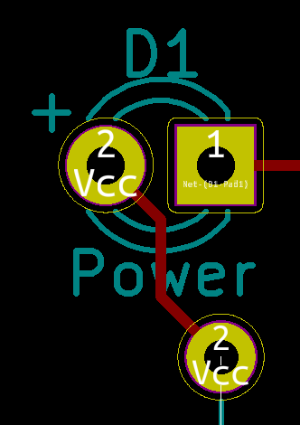
Bad PCB Layout

With our LED here the Vcc flows to the Pin #2 (anode of the LED).  While doing so, it comes quite close to Pin #1.  In this case, there is no reason to route so close to the enemy pad.  The better habit to form would be to start drawing the trace at the anode and avoid Pin #1.

Good Example

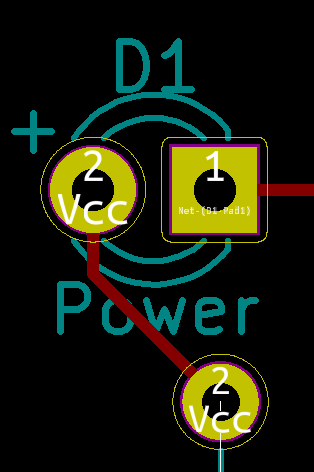
GoodLayout

In this good example, I started with Pin #2 of the LED (anode) and came straight down before angling towards Vcc.  The distance between the Pin #2 trace and Pin #1 is maximized without any down sides.

Reality

In reality, this is an incredibly simple example and the LEDs pins give plenty of clearance to solder them later.  So, this example sucks.  However, by developing a habit of maximizing space between enemy traces and pads, we reduce the odds of messy soldering situations.  Last week I received a PCB in SOIC-8 SMD footprints.  I could have taken the approach outlined here with no downside, but instead, I routed my enemy traces way too close to the tiny SOIC-8 pads.  The end result was I ruined one of the pads on the board and wasted 3 hours as I had to solder up a new board.