Posted on Leave a comment

Microchip 25LC256 EEPROM on STM32 Blue Pill and Arduino

For the big, bad synth project, I needed an EEPROM.  I selected the Microchip 25LC256 from Digikey simply because it had excess capacity (256k) and was thru-hole.   (I always recommend this approach when jumping into a new arena of unpolished prototyping).  I had never worked with external EEPROM before.   It turns out that EEPROM is fairly straight forward.  You pick an address and you write to it.  It’s not all that different from how a file cabinet works.  When you run out of room in one drawer, you move on to the next drawer.  Sometimes you want to put stuff in separate drawers even if they aren’t full.  These”drawers” are known as pages.

The page size in the Microchip 25LC256 is 64 bytes.   At the moment, each preset for my synth requires about 40 bytes, so this means I’m gonna waste 24 bytes per page in the interest of staying organized.  There are many other chips in the 25LCxxx series of varying sizes.  The smaller capacity EEPROM chips use smaller page sizes, which means I’ll need to dedicate multiple pages to each preset.   You’ll see a function to write a 64 byte array to the EEPROM all at once below.  This is significantly faster than writing one byte at a time as there is a 5ms penalty after finishing up the write process no matter if you are writing 1 byte or 64 bytes.

Of course, it took longer than I hoped to effectively use the Microchip 25LC256 EEPROM.  What else is new!    You’ll certainly want to adapt these functions below to suit your needs, but this code does work on an STM32 Blue Pill in PlatformIO using the Arduino framework.  I suspect the critical piece I was missing was slowing down the SPI clock. You’ll see this code uses a clock divider of 16.  According to the datasheet, the larger the Vcc, the faster clock you can get away with.

I’m moving these functions into a dedicated Microchip 25LCxx library which I’ll give away when its ready.  For now, here’s the working code in a rough format.


#include "Arduino.h"

#include <SPI.h>

byte pin_SS2 = PB12;

HardwareSerial Serial3(USART3); // PB11 (RX3)  PB10   (TX3)

void EEPROMsetup()
{
  //SPI_2.begin();
  pinMode(pin_SS2, OUTPUT);
  digitalWrite(pin_SS2, HIGH);
}

byte EEPROMread(uint16_t address)
{
  byte read_buffer = 0;
  digitalWrite(pin_SS2, LOW);
  SPI.transfer(0b00000011);         // Set EEPROM to read mode.
  SPI.transfer16(address);          // Send the 16-bit address
  read_buffer = SPI.transfer(0xFF); // A dummy byte is sent to read the buffer.
  digitalWrite(pin_SS2, HIGH);

  Serial3.print("Reading:  ");
  Serial3.println(read_buffer);
  Serial3.print("Address:  ");
  Serial3.println(address);
  Serial3.println("");

  return read_buffer;
}

void EEPROMwriteByte(uint16_t address, byte value)
{
  digitalWrite(pin_SS2, LOW);
  SPI.transfer(0b00000110); // WREN write enable latch.
  digitalWrite(pin_SS2, HIGH);

  digitalWrite(pin_SS2, LOW);
  SPI.transfer(0b00000010); // WRITE INSTRUCTION
  SPI.transfer16(address);
  SPI.transfer(value);
  digitalWrite(pin_SS2, HIGH);
  delay(5); // Taken from datasheet.  This slows down EEPROMWriteByte a bit, but if a second write is started before the
  // first can be completed, it will ignore the second one.  That's bad.   While the write is in progress, the STATUS register
  // may be read to check the status of the Write-in-process (WIP) bit (Figure 2-6).  I haven't tried that one yet.

  Serial3.println("Write complete");
}

byte EEPROMreadStatus()
{
  byte read_buffer;
  digitalWrite(pin_SS2, LOW);
  SPI.transfer(0b00000101); // Red STATUS register
  read_buffer = SPI.transfer(0xFF); // A dummy byte to read the buffer.
  digitalWrite(pin_SS2, HIGH);
  return read_buffer;
  // Serial3.print("Status:  ");
  // Serial3.println(read_buffer);
  // Serial3.println("");
}

void EEPROMWritePage(uint16_t page_num, byte *save_this_array)
{
  // Pages are 64 bytes.  I'll give each preset a page for simplicity.

  digitalWrite(pin_SS2, LOW);
  SPI.transfer(0b00000110); // WREN write enable latch.
  digitalWrite(pin_SS2, HIGH);
  digitalWrite(pin_SS2, LOW);
  SPI.transfer(0b00000010); // WRITE INSTRUCTION

  SPI.transfer16(page_num * 64); // Send address of page number.  Must start at n * 64.

  for (int i = 0; i < 64; i++)
  {
    SPI.transfer(save_this_array[i]); // WRONG WRONG WRONG WRONG WRONG
  }

  digitalWrite(pin_SS2, HIGH); // close up the write process
  delay(5);                    // See TWC in datasheet https://ww1.microchip.com/downloads/en/DeviceDoc/25AA256-25LC256-256K-SPI-Bus-Serial-EEPROM-20001822H.pdf

  Serial3.println("Page Write complete");

}

void setup()
{
  SPI.begin();
  SPI.setClockDivider(SPI_CLOCK_DIV16); // 72Mhz / 16 = 4.5Mhz
  SPI.setBitOrder(MSBFIRST);

  Serial3.begin(19200); // PB11 (RX)  PB10   (TX)
  Serial3.println("Serial3: 3");
  EEPROMsetup();

  byte preset_arr[64];

  for (int i = 0; i < 64; i++)
  {
    preset_arr[i] = i;
  }

  EEPROMWritePage(0, preset_arr);

  EEPROMWritePage(2, preset_arr);

  // Read Page Two   Page 2 starts at 64*2 and ends at (64*3 - 1)
  for (int i = 128; i < 192; i++)
  {
    EEPROMread(i);
  }

  EEPROMwriteByte(50, 21);
  EEPROMwriteByte(52, 22);
  EEPROMwriteByte(30, 23);

} // end of setup

void loop()
{
  EEPROMread(50);
  EEPROMread(52);
  EEPROMread(30);
  delay(500);
}


Posted on Leave a comment

STM32 Blue Pill ADC Values Too Low in PlatformIO


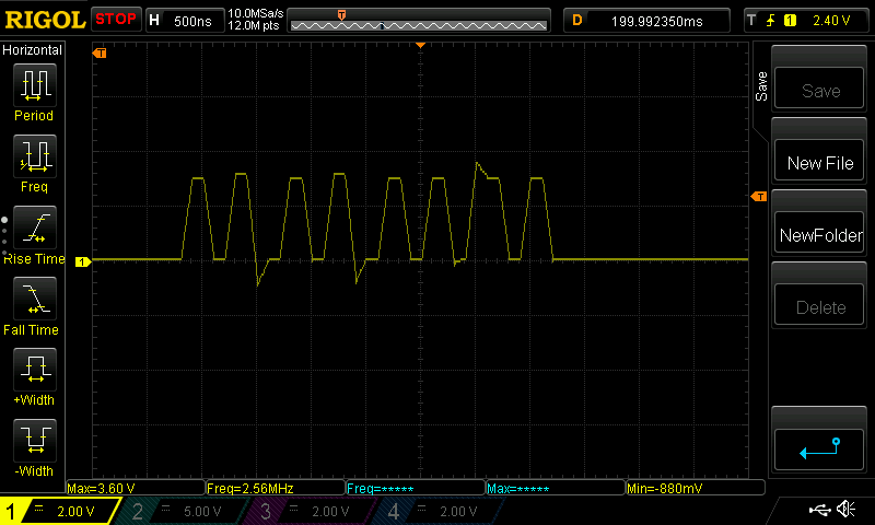
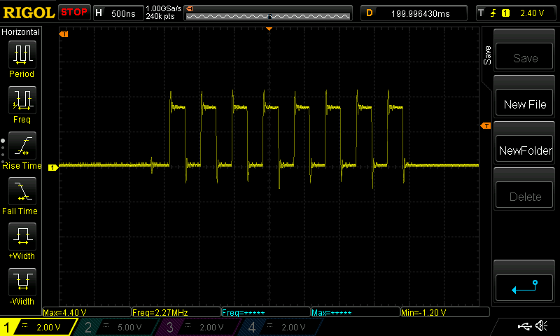
I kept getting values that were way too low when feeding an ADC on the STM32 Blue Pill 3.3V. I should have been getting values that were around 4000 and instead I was closer to 800.

Solution
1) The default ADC in the Arduino library is set to 10-bit resolution. This is what you normally get with analogRead(). To change it, put this in your setup(). Read more about it here: https://www.arduino.cc/reference/en/language/functions/zero-due-mkr-family/analogreadresolution/

analogReadResolution(12);

Notes
— This would have been a much easier problem to solve if i had been getting values of around 1000. It turns out that my ADC pin wasn’t getting exactly 3.3V. There was a voltage drop in my system – I’ve got a huge mess currently hooked to the Blue Pill – that knocked it down to around 3V. Normally, calculating bit resolution in decimal is 2^x – 1. So 2^10 – 1 = 1023.

— PlatformIO had nothing to do with the error. I’m new to PlatformIO and never know if my issues are due to the STM32’s specific needs, the Arduino library, or some kind of PlatformIO specific issue. It seems that as long as the hardware is setup correctly and
#include <Arduino.h>
is at the top of the program/sketch/whatever, PlatformIO has no ill effects. The problems I have had aren’t the fault of PlatformIO but from adapting libraries intended for AVR to STM32F1.


Posted on Leave a comment

Genuine STM32 Blue Pill vs CS32F103C8T6 Clone

I’m troubleshooting a synth design and looking at the data on the SPI bus.  I have 10 STM32 clones (CS32F103C8T6) of the STM32F103C8T6 around and decided to try them out since they have the correct USB resistor.

I was getting the following error in PlatformIO.

Warn : UNEXPECTED idcode: 0x2ba01477

To get the clone to work, I had to change stm32f1x.cfg which I found in C:\Users\YOUR_WINDOWS_USER\.platformio\packages\tool-openocd\scripts\target\

I changed set _CPUTAPID 0x1ba01477 to set _CPUTAPID 0x2ba01477.  If I need to go back to the real Blue Pill, I’ll have to change this back again.

I started with the clone and then switched to the real one.  The scope shows some interesting results.  This is data from the SPI bus.  The circuit is 100% identical in both cases.

CS32F103C8T6 Clone SPI Data

Genuine STM32F103C8T6 SPI Data

I’m not sure if the clone just can’t handle the speed or if there’s some kind capacitance slowing it down.  Regardless, the SPI output of the clone is so bad that I’ll have to check the timing diagrams for my SPI-receiving chip.  I don’t have this problem with the genuine STM32.

If anyone knows a solution to get the clone to behave, please tell me.  Otherwise, I’ll have to view these Chinese clones as WAY too expensive once time is factored in.