STM32 HAL – Hard n Fast – Cheat Sheet
Remember all those functions in STM32 HAL you can’t remember? This cheat sheet solves that.
Remember all those functions in STM32 HAL you can’t remember? This cheat sheet solves that.
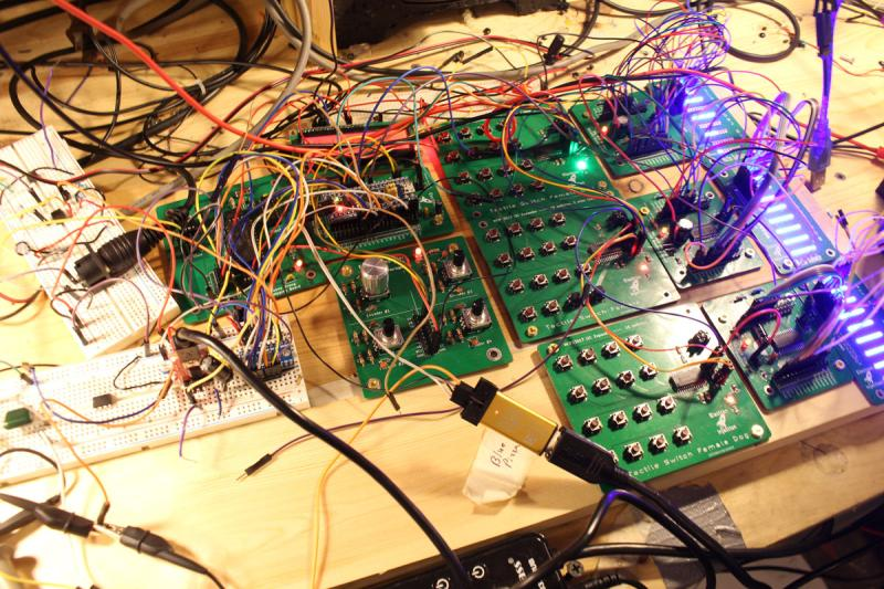
Believe it or not this is a fully functional music synthesizer with fully every possible parameter tweakable and can save presets. The synth sound horrible, but that was by design. The YM3812 chip is from an old Soundblaster card from back in the Reagan days. This thing sounds like bad dog stuff. It’s so bad … Read more
This code turns the onboard PC13 LED of the STM32 Blue Pill on when a MIDI NoteOn message is received and turns the LED off when a MIDI Noteoff message is received. It’s my preferred way to confirm that a MIDI circuit is working. It relies on the Arduino MIDI Library.
The Problem: The STM32 Blue Pill sometimes dies for no apparent reason. On the PSU, it’s pulling 30mA and then for now apparent reason, the current draw reduces to 10mA (for the power indicator LED, presumably) and the microcontroller appears dead. It only seems to occur when powered from a power supply to the 5V … Read more
The smooth fading of LEDs is possible, but it’s best to have 16 bits to work with and ditch the linear world. // My code dutyCycle = pow(1.03, time_increment); // Math equivalent y = 1.03^x Above is the most interesting piece of code today. dutyCycle for this code is a number from 0 – 65535. … Read more
For the big, bad synth project, I needed an EEPROM. I selected the Microchip 25LC256 from Digikey simply because it had excess capacity (256k) and was thru-hole. (I always recommend this approach when jumping into a new arena of unpolished prototyping). I had never worked with external EEPROM before. It turns out that EEPROM is … Read more
Here’s the “Hello World” edition of getting access to USART2 and USART3 on an STM32 Blue Pill in PlatformIO using the Arduino framework. /* lib_deps = NONE # Using a library name ——– Platform.ini Settings———- [env:bluepill_f103c8] platform = ststm32 board = bluepill_f103c8 #board = bluepill_f103c8 framework = arduino upload_protocol = stlink lib_compat_mode = soft */ … Read more
I kept getting values that were way too low when feeding an ADC on the STM32 Blue Pill 3.3V. I should have been getting values that were around 4000 and instead I was closer to 800. Solution 1) The default ADC in the Arduino library is set to 10-bit resolution. This is what you … Read more
I’m troubleshooting a synth design and looking at the data on the SPI bus. I have 10 STM32 clones (CS32F103C8T6) of the STM32F103C8T6 around and decided to try them out since they have the correct USB resistor. I was getting the following error in PlatformIO. Warn : UNEXPECTED idcode: 0x2ba01477 To get the clone to … Read more